
Precision Metal Machining Services On Demand
Turning, milling, coordinate boring and surface/cylindrical grinding of metals. Precision manufacturing of components across all complexity classes according to CAD drawings, 3D solid models or physical samples. Reconditioning of shafts and hydraulic cylinder rods.
Precision Metal Machining Services On Demand
Technical Production Capabilities
Parameter
Specification / Capacity
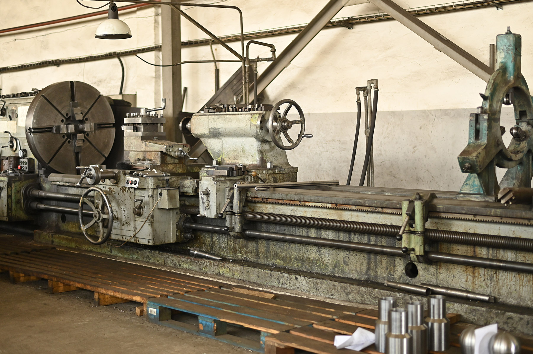
- Conventional Turning Operations
Diameter up to Ø 1,000 mm, length up to 5,000 mm
- CNC Turning Center
Chucking Ø 55–320 mm, turning length up to 900 mm
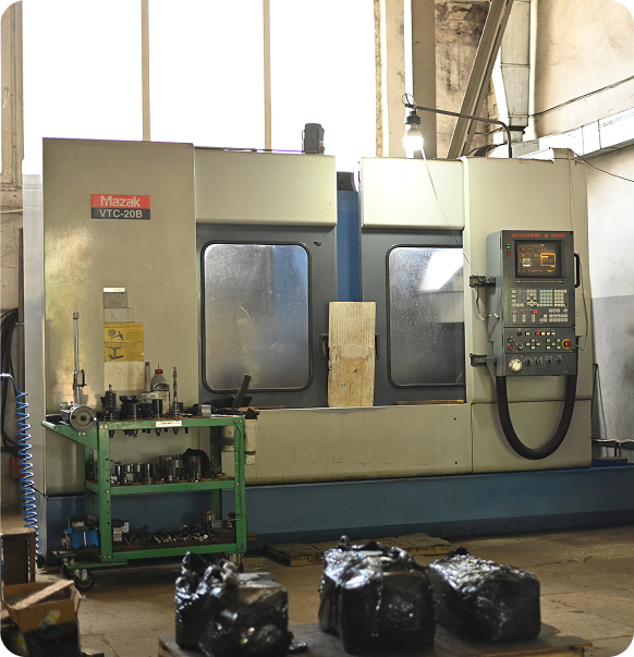
- MAZAK VTC-20 Vertical Machining Center
Table size 1,460 × 510 mm, max table load capacity up to 800 kg
- Coordinate Boring Operations
Hole diameters up to Ø 250 mm, boring depth up to 750 mm
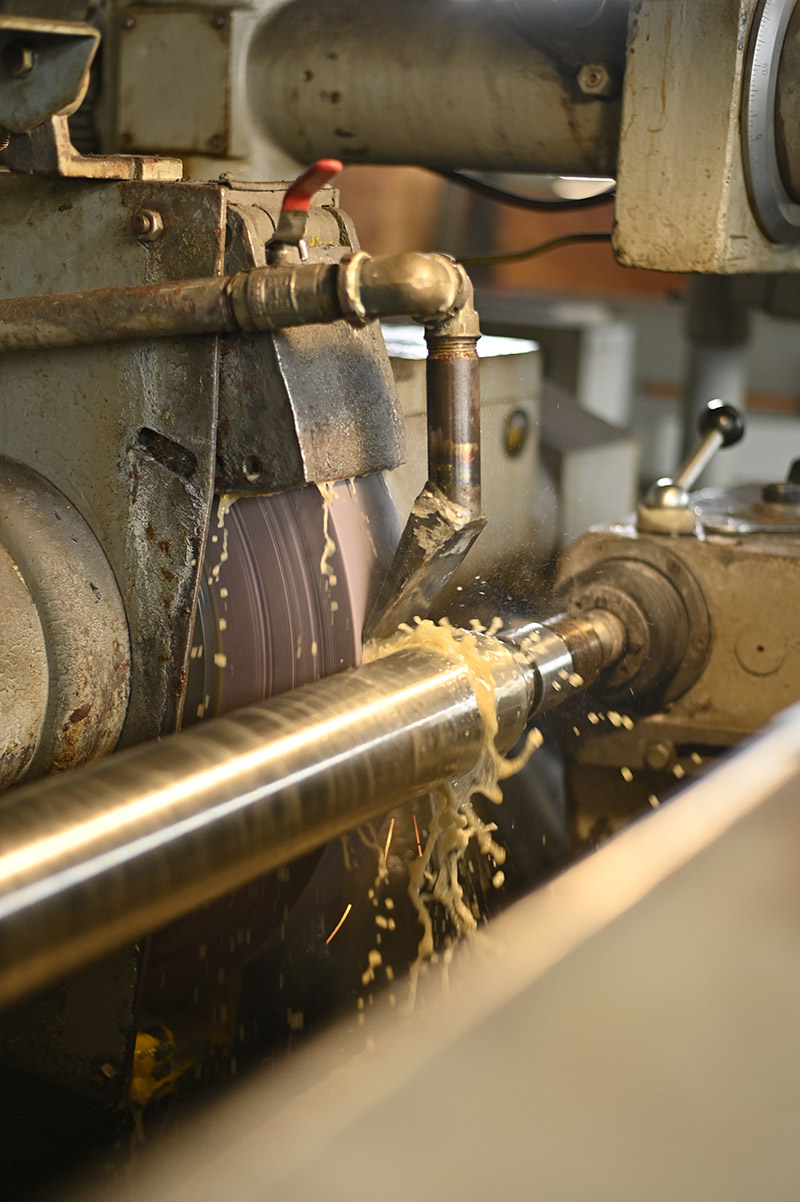
- Cylindrical Grinding Operations
Diameter up to Ø 400 mm, grinding length up to 2,000 mm
- Workpiece Materials Processed
Structural carbon steels, alloy steels, stainless steels, cast iron, aluminum alloys, brass, and copper
Machining Operations and Manufacturing Capabilities
01
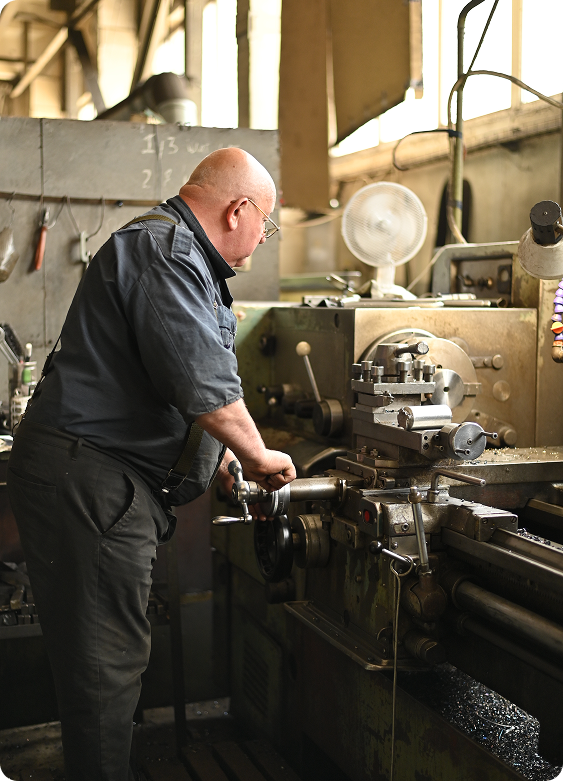
Turning Operations
- Heavy-duty turning of parts up to Ø 1,000 mm in diameter and up to 5,000 mm in length.
- High-precision CNC turning for workpieces up to 900 mm in length.
- Thread chasing/threading, internal boring, facing, and precision machining of drive shafts, axles, guide bushings, and connection flanges.
02
Milling Operations
- Horizontal Milling: Working table 1,600 × 400 mm, clearance/machining height up to 420 mm.
- Vertical Milling: Working table 1,250 × 320 mm, component envelope up to 700 × 420 mm.
- MAZAK VTC-20 CNC Machining Center: Working table 1,460 × 510 mm; axis travels: X = 1,120 mm, Y = 510 mm, Z = 510 mm; max table load up to 800 kg. 3D contoured surface milling of complex hydraulic manifold blocks, housings, brackets, and structural frames.
03
Coordinate Boring Operations
- Table working envelope / center distances up to 500 × 315 mm.
- Precision line boring of holes up to Ø 250 mm in diameter.
- Line boring depths up to 750 mm.
- High positioning and repeatability accuracy for critical structural assemblies.
04
Precision Grinding Operations
- Cylindrical Grinding: Workpiece diameters up to Ø 400 mm, lengths up to 2,000 mm (for drive shafts, plungers, and hydraulic cylinder piston rods).
- Surface Grinding: Magnetic chuck 560 × 190 mm, working table surface 630 × 300 mm, maximum workpiece footprint up to 710 × 235 mm.
05
Component Reconditioning via Automated Weld Overlay (Cladding)
- Reconditioning worn bearing journal seats, keyways, and external friction surfaces of shafts and rods.
- Processing diameters up to Ø 400 mm, lengths up to 2,000 mm.
- Follow-up CNC finish turning and precision cylindrical grinding to nominal engineering drawing tolerances.
Machine Fleet: Delivering High Precision and Quality
MAZAK VTC-20 CNC Machining Center (Japan): Engineered for complex multi-port manifold bodies and prism components, ensuring high throughput and tight tolerances.
Heavy & CNC Lathes: Precision shaft and cylinder rod turning up to 5,000 mm in length.
Precision Coordinate Boring Mill: Precision machining of multi-cavity bores and bearing fits.
Heavy Cylindrical Grinding Machine: Grinding lengths up to 2,000 mm.
Surface Grinder: High-precision flat grinding for manifold mating surfaces and wear plates.
Reliability Backed by Proven Capabilities
- Fully Integrated In-House Production
- All machining, cladding, and finishing stages executed in a single facility under continuous quality gate control.
- Modern Machine Tool Fleet
- Machine tools from global manufacturers guarantee strict ISO tolerance classes, fine surface roughness finishes, and serial repeatability across production batches.
- Track Record in Complex Remanufacturing
- Automated cladding of shafts/rods, coordinate boring of heavy housings, and precision repair of imported hydraulic components.
- Quality Assurance Guarantee
- Every machined part undergoes metrological inspection. Technical passports and raw material mill test certificates (MTC) are issued upon request.
Frequently Asked Questions
What drawing formats do you accept for production?
We accept engineering CAD drawings in PDF, DWG, and CDW formats, as well as 3D solid models (STEP, STP, SLDPRT). Reverse engineering from an actual physical sample is also available.
What are your minimum and maximum manufacturing turnaround times?
We accept engineering CAD drawings in PDF, DWG, and CDW formats, as well as 3D solid models (STEP, STP, SLDPRT). Reverse engineering from an actual physical sample is also available.
Do you accept emergency rush orders?
We accept engineering CAD drawings in PDF, DWG, and CDW formats, as well as 3D solid models (STEP, STP, SLDPRT). Reverse engineering from an actual physical sample is also available.
What technical documentation is supplied with finished parts?
We accept engineering CAD drawings in PDF, DWG, and CDW formats, as well as 3D solid models (STEP, STP, SLDPRT). Reverse engineering from an actual physical sample is also available.
Calculate the Cost to Machine Your Part
Attach an engineering drawing (PDF, DWG, CDW), a 3D CAD model, or clear photos of the part. Our engineering team will review your specifications, verify tolerances, and prepare a detailed commercial quotation.